- September 23
|
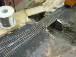
In order to prevent the points of this turnout from occurring on a bridge, a gantlet section was installed. This is based on a prototype in Bellows Falls VT.
|
|
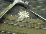
The installation of a new signal starts with "Dig we must".
|
|
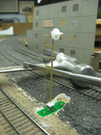
The circuit board is in place and the unpainted signal installed. The signal heads and base were cast in polyester by David Lambeth, who presented us with a bag of them.
|
|
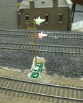
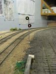
It lights up!
|
|
All done.
|
|
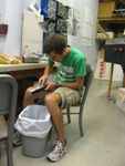
New member Paul is scraping down some second-hand passenger cars. They're tough--the car shells are made from aluminum extrusion.
|
|
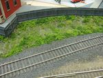
Returned (briefly) member David installed a fence, and new member Chloe put in some weeds beside it.
|

|
She made a driveway too.
|
- September 26
|
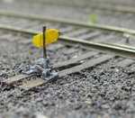
In addition to his other work while he's been away, David Lambeth cast some switch stands. They are very small and delicate. Here is the first one, installed in F-yard. The post carrying the flag is .020 inches diameter. Although we've built operating switch stands in the past, this one doesn't move.
We also had a visit from computer, business and academic veteran Dr Edward Fredkin.
|
- September 30
|
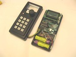
At long last, the prototype radio-linked cab made an appearance. It was able to run a train!
Note rechargeable batteries at the bottom, metal strips at the sides which contact the user's hand (no need for an "On" switch), and case borrowed from Cab 6. The large green component that looks like a resistor is actually the inductor that's part of the step-up voltage converter. It seems to run for about 3 hours on a full battery. Most of the power goes to run the LCD backlight.
The cabs feature bidirectional communication, with data from the server being used to place text on an 8x2 LCD, and run signal lights and a beeper.
|
|
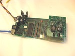
This is the "base unit" for the radio cabs. A circuit board from the cab construction program was sacrificed to place the receiver and transmitter modules on, wired back to the processor on one of our general-purpose project boards.
The transmitter is the smaller of the two modules, and the receiver is the larger one. Each has its own antenna, the cylindrical devices at the bottom.
The design issue that remains to be determined is how many units can run on one channel. All the boards communicate at 916MHz, so transmitters must be switched on and off at precise times. It's also not clear what rate we can use to send digital data. At present the system uses 13KB, but it can probably run faster. We think we can get "several" but not "many" units working at once.
|
|
|
